myQrc – test completed
Leave a reply
I just upload the last and final version of the myQ release candidate on github
All the software has been debugged and tested.
All the functionalities are now stable.
I tested in different options (debug mode, netscan activated, sensor log) and the result is that I can run the main loop every 10 ms and get sensor data every 6 ms.
It can happen to have a delay on the sensor data loop when a log is added ( 2/3 ms).
I removed the webserver from the list of test to do, so it is not supported in this version of the software. The main reason is an instability when runnin gon raspberry. I have to investigate a more robust way to manage the comunication via browser.
Next time I will write a post the drone will be just landed…(after its first flight!!!)
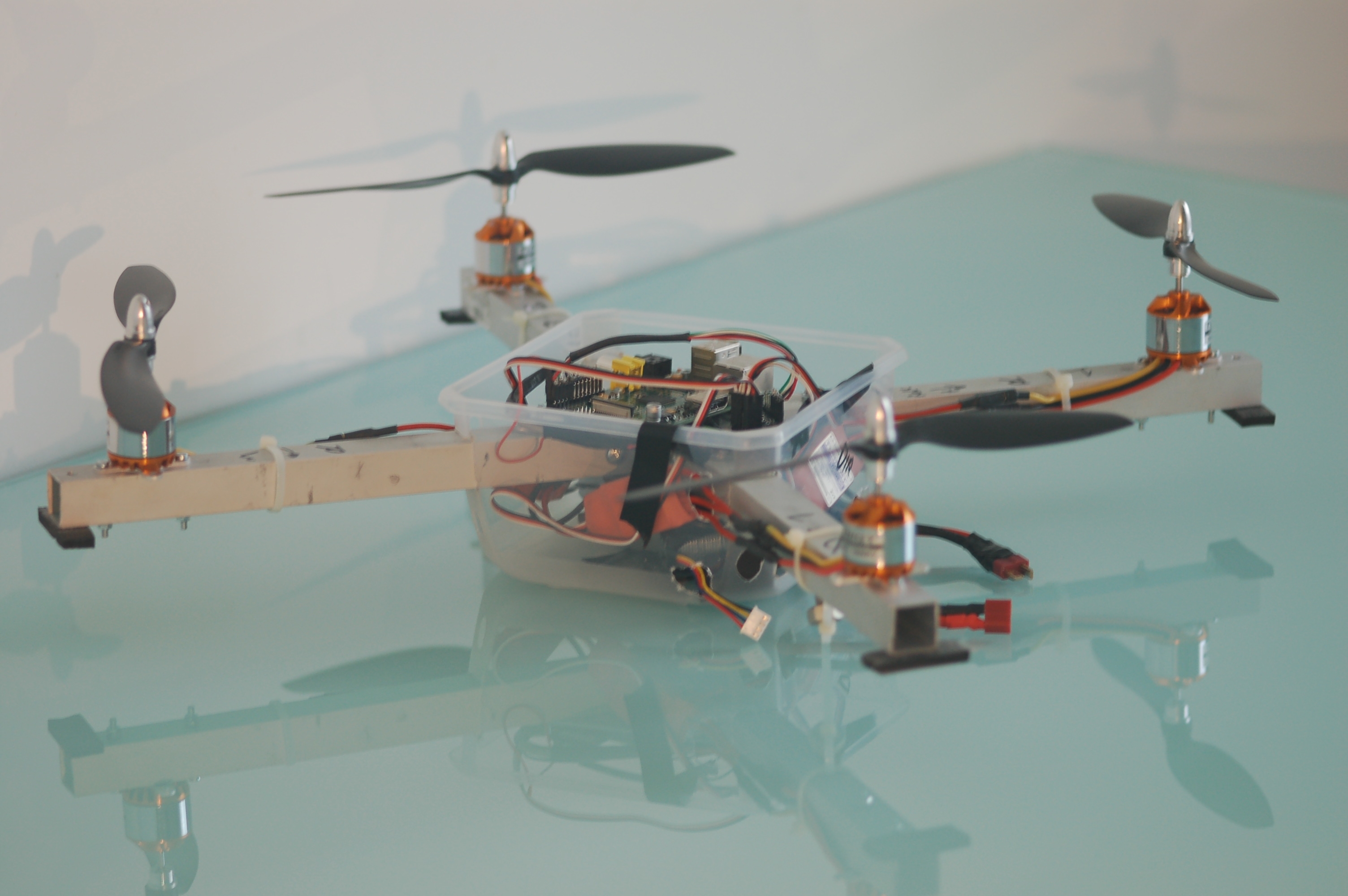
Ready to Fly (almost…)
Here it comes!The hardware is ready,it’s time to start the flight tests…

Alfa3.test. Here it comes the python code
So now ,after some additional tests, here I added the software code: alfa3
All the basic components necessary to build a quadcipter sw are now implemented.
This is list of the modules developed:
This is list of the modules developed:
- motor.py
- sensor.py
- MPU6050.py
- pid.py
- rc.py
Any of those modules includes a specific object.I’ll plan some time to review the python page with a detailed help for each module.
Here I want just to summarise the main aspects.
rc is the new entry in this alfa3test session.it is an object that works in parallel thread.It is just waiting for input from user. In this particular case the input is coming from the keyboard,but the same approach it is possible (I’ m working on it and a tutorial is close to be ready) to get input from a webserver running on rpi.
Motor is an object that manages the motor speed trou ESC. It uses the RPIO library to generate the PWM.
Sensor is an object that works in a parallel thread. Every around 6ms it can update the info from the gyroscope and the accelerometer ,quadcopter inclination and rotational speed.
MPU6050 is a pure interface between raspberry and sensor hardware. If you want to use a different sensor it is just needed to build this specific class.
Pid is the object that includes the calculatio for the proportional , integral and derivative control.
Alfa3test. PID introductionand more…
Starting with this series of tests Alfa3,I added some new features that move the project to the final setup.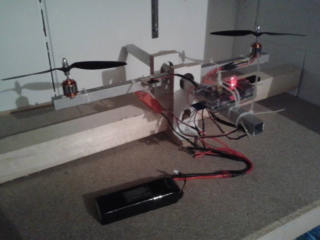 In particular I add the following modification that allow the system to work wireless:
 In particular I add the following modification that allow the system to work wireless:
- I added a second ESC and a second motor.
- I modified the connector board adding a new 3 pin connector (C in the photo) where there is the zero volt (black wire), the signal (white wire) that is bridged with the 4th signal (green wire), and also added the 5 volt (red wire) .
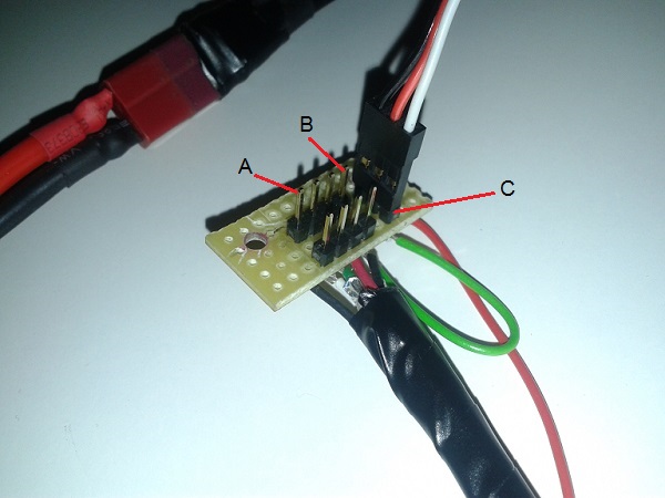 In this way I can choose if rpi is powered by the ESC (C connection) or not (B connection).
 - So the schema for this test consist of the connection of motor M[0] in A and motor M[1] in C.
- I connected also my wifi dongle in the rpi usb port. I discovered that neither the pc nor the wifi dongle can act as access point. You can verify this using the comand:

iwconfig ap
So I used my smartphone activating the router wifi function,building up a network including the PC and the rpi.
Below the references used in the test:

- M[0] turns counterclockwise, the red wire is connected to the “T” wire of the esc (the one that is closer to the T of the Turnigy logo),and the yellow wire to the “Y” wire , the black wire with the center wire of the esc.
- M[0] mounts a standard left prop.
- M[1] turns clockwise, the yellow wire is connected to the “T” wire of the esc ,and the red wire to the “Y” wire ,the black wire with the center wire of the esc.
- M[1] mounts a right prop. (marked R).
- According to the position of the IMU,I have a negative roll rotation if M[0] moves down.
I did already some tests with this configuration. In the next post the first results and the description of th enew sw module rc.py that is the remote control module.
Alfa1 test.Preparation
During the last wekend I have been busy,so it was not possible to continue the testing.
By the way now it comes a new post where I describe the code I created for what I called alfa tests, a session of experiments to prepare the final code.
Alfa1 test includes the following functionalities:
- manual motor jogging
- IMU reading
- data logging (motor w,and IMU angles)
The actions I want to take during this test are:
- verify the disturbance on IMU data due to motor vibrations
- test different IMU filter values
- start the motor and try to understand which is the hover w (motor angular speed) according to the current configuration
- Start the motor and understand how a deltaw can influence angle of the quadricopter
- mount different weights on the quadcopter arm and see the different wh (hover w) in order to verify my math model.
- measure the actual motor angular speed with my smartphone (just curious abuot the possibility to measure the real w with a sound spektrum analyzer).
Hope to start tomorrow the alfa1 test, than I will share the code.
Class sensor.py ready!
After some complementary activities (build a new table for next experiments, for example) I finalized the test on the IMU and created this sensor object that can run in a parallel thread , so I can get last updated sensor information anytime (every 5 -8 ms) while my main quadcopter loop is running.
You can find and download the sensor_test example.When you run it you can see on the terminal the current roll,pitch and yaw of your IMU.
You can find and download the sensor_test example.When you run it you can see on the terminal the current roll,pitch and yaw of your IMU.
The available data are: angular position [deg],angular rate[deg/sec], linear acceleration[m/sec]
The main differences respect the IMU_test are:
- I saw that the mpu6050 initialization of same parameter can fail.The order on how you set the IMU parameter can affect the setting itself. So I added a function to verify the parameters are in fact what I decide.
- The accelerometer vector has been normalized, so the lenght ,when not moved is equal to the gravity. this can help if I want to integrate it to extimate the linear speed and the linear movement
- the class sensor.py can run in a parallel thread, so anytime I can have the current sensor values.
- minor adjustments done on the naming of the variables.
Next steps are:
- Buy some connectors and do some soldering to have a final version of the wiring
- mount the sensor on the frame and test it with running motors and see if i need more severe filtering.
Tutorial: How to read data from IMU
In the previous post I described how to setup raspberry pi for connection with the IMU.
Now it is time to see how to read some data from the sensor.
First yuo need sw that manage the i2c interface.there are many examples.You can find one called adafruit_i2c.py on github.
Then it is necessary to have the code specific for the sensor,in my case a MPU6050.
I tryied for some days to build my own code, but I encountered problems related to unconsistent results: even if I did not move the sensor, the returned results were always different. I suspect it was a problem on how I formatted the values.
Finally, Thanks to the great job done by Hove in his blog, I used his code and I’m now able to collect correct data from the sensor.
I did some minor modification and prepare this IMU_test files.
So I started some preliminary tests to verify which is the sensor behaviour.
I fixed the sensor on a bar ,horizontally, than turned the bar by a known angle ( 13 degrees,measured with my smartphone level) then move back to horizontal.

I recorded on a file the sensor data : acceleration along axis (from ACCelerometer) and rotational speed (from GYRO scope). On excel sheet I calculated the angle around x respect the ACC and respect the GYRO:
- rx ACC=DEGREES(ATAN2(accZ+9.8;accY))
- rx(i) GYRO=wx(i) *dt+wx(i-1)
Below you can see the graph.

I underline in the picture the 2 tipical problems on the IMU :
- the Gyro drift (you can see an angle of 1 degree while it reality it was 0)
- the Accelerometer sensibility to noise.
So next development step is to filter/reduce this 2 problems by combining the 2 sensors results.
IMU Sensor Installation
Since a week ago, I ‘ve been looking into my new IMU: Inertial Measurement Unit.
I bought from e-bay a MPU6050, a sensor including:
- a gyroscope that can return the angular speed around the 3 axis x,y,z.
- an accelerometer that can return the linear acceleration along the 3 axis x,y,z.
This sensor can communicate trou I2C interface.
Below the electrical drawing:
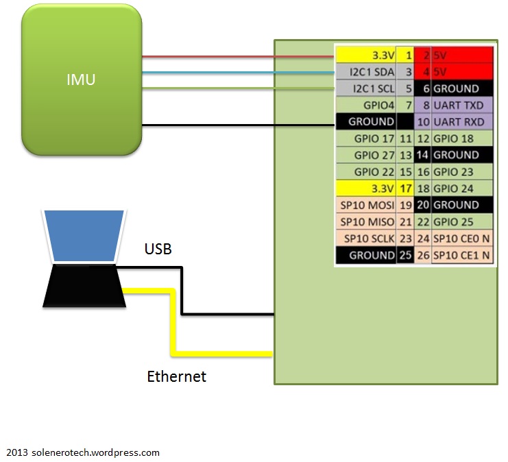

For the sw installation I fuond a clear tutorial on the Adafruit website ,so I just report here a memo for the necessary steps:
in sudo nano /etc/modules add:
- i2c-bcm2708
- i2c-dev
sudo apt-get install python-smbussudo apt-get install i2c-toolsin sudo nano /etc/modprobe.d/raspi-blacklist.conf comment:
- #blacklist spi-bcm2708
- #blacklist i2c-bcm2708
Now ,running the command sudo i2cdetect -y 1 yuo have to see the address 0x68, corresponding to the default sensor address.
SW Dev 2: quadcopter.py
Hello , I’m publishing the new module quadcopter.py.
This object has the main scope to be the controller of the quadcopter.
It includes 4 motors (from motor.py class) and the necessary interface for manage the commands coming from user.
This version is preliminary since it does not iplements all the functionality but it can be considered the first step for the qpi logics.
Let’s see in details what is included in the modules for qpi_test2
motor.py is getting more robust. i added some procedures to manage the motor parameters like setSimulation and getSimulation.
I also added a check to verify if the RPIO library is available.In case it can work anyway in simulation mode.
Procedure motor.start implements a sequence for initialize the ESC (it must to be verified yet)
Procedure motor.stop that stops immediatly the motors.
quadcopter.py can manage 4 motors. the motors are defined as a list (array) so it is possible to direct access any motor with its index, for exemple: self.motor[1].start
it includes procedures to move the quadcopter, like increaseThrottle,decreaseThrottle, increaseRoll,decreaseRoll ,increasePitch,decrease Pithc, increaseYaw,decreaseYaw and hover.
For the moment those procedures are used directly on the motor speed, but in next releases they will work on angles and the conversion has to be managed
For this reason this class can be used only for development activity to have an overview of the whole flow.
qpi.py is again the user interface, but i added a minimal graphical interface.
it is possible start the motors by pushing 0-1-2-3
- increase motor rotation with a-z , s-x,d-c,f-v
- play with throttle y-n, roll i-m, pitch j-k yaw g-j, hover h
you can test it even if no motor is connected, but also in a pc running linux, different from raspberry pi
SOFTWARE Installation
Hello, today I inaugurate the english version of my blog.
As soon as I can I’ll translate also the static pages.
By the way, consider that this project is based on raspberry pi (rev B) for the motion control of the quadcopter.
Here there is a description of the necessary sw installation.
I’m using a laptop with ubuntu, and there I installed ninja IDE, direcly from ubuntu software center.
On this laptop I create a folder home /home/pyton/qpi.
Considering the rpi installation:
I copied a 2013-02-09-wheezy-raspbian.img on a 2GB SD.(right now you can find an updated verison of raspbian, on the rpi website here: link
Start rpi connected on a monitor,my case was tv via hdmi wire , mouse and keyboard and a ethernet cable.
Leave the default setting in the config.
Now you can disconnect all from rpi except the ethernet wire.
On the router I defined a static address :192.168.0.50 , related with rpi mac address. (i have a netgear router and it waas really intuitive to set it ).
From the laptop , on the terminal use [See note below if you encounter problem with ssh]:
ssh pi@192.168.0.50
password : raspberry
Now yuo are using rpi from the laptop
Execute:
$ sudo apt-get undate
$ sudo apt-get upgrade
The update/upgrade can take up to one hour.
Since I ‘ll use rpi to pilot the motors I ‘nned to install the library that can manage the GPIO in rpi.
This library RPIO allows to set any output as PWM:
$ sudo apt-get install python-setuptools
$ sudo easy_install -U RPIO
Now let’s see how to set up the Wifi Connection via usb dongle.
Do not connect the usb dongle.
Install the wpa_supplicant utility:
$ apt-get install wpasupplicant
Run the utility to create the password_phrase:
$ wpa_passphrase My_WiFi_SSID mypassword
Yuo will get this output.
network={
    ssid="My_WiFi_SSID"
    #psk="mypassword"
    psk=b2abb0fcd2f4527e11817de0823a57bb19ba4622f4595062c94ec4dd1370b5fe
}
Copy the psk value.
Run the editor to modify the /etc/network/interfaces
$ sudo nano /etc/network/interfaces
Modify the file (pasting the psk value):
...

auto wlan0
allow-hotplug wlan0
iface wlan0 inet dhcp
  wpa-ssid "My_WiFi_SSID"
  wpa-psk b2abb0fcd2f4527e11817de0823a57bb19ba4622f4595062c94ec4dd1370b5fe
Switch off RPi.
Connect teh dongle and disconnet the ethernet wire.
Restart rpi and you are on line.
Set the router in case you want a fixed ip address for the wifi connection.
Link:
NOTE: recently I clean up my laptop and installed ubuntu 13.10 on it.
From that moment it has been not possible to use ssh using wired connection.
So I solve it modifying the rpi eth0 configuration manually.
pi@raspberrypi ~ $ sudo nano /etc/network/interfaces
iface lo inet loopback
#iface eth0 inet dhcp
allow-hotplug eth0
iface eth0 inet static
address 192.168.1.2
netmask 255.255.255.0
gateway 192.168.1.1
In the same way, in the laptop I defined a static ip address 192.168.1.1
List of Material
Following the suggestion of oddcopter Itoday I bought some material.
See the day by day updated material list here